
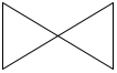
Gate valve
The general on/off valve. Fully open or fully closed, not for throttling.
A P&ID (piping and instrumentation diagram) shows how a process plant is piped and controlled: every pipe, valve, pump, tank and instrument, and the signals between them.
Instrument symbols and tags follow ISA-5.1 in most of the world. Equipment shapes vary a little between companies, so every P&ID set starts with a legend sheet; the shapes below are the common ones.
Free. In draw.io, open the library with File › Open Library from › Device. Each symbol below also downloads as SVG, or copies straight into draw.io.
A valve is two triangles meeting at their tips; what sits in the middle tells you the type. Valves are drawn open unless marked otherwise.
The general on/off valve. Fully open or fully closed, not for throttling.
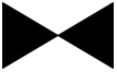
Filled triangles mean the valve is normally closed, for example a drain or bypass.
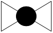
Used to throttle (regulate) flow. Most control valves are globe valves.
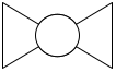
A quarter-turn on/off valve with a bored ball inside.
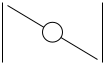
A disc that turns in the pipe. Light and compact, common on large water and air lines.
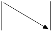
Lets flow pass one way only, in the direction of the arrow. Stops backflow into a pump.
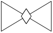
A quarter-turn valve with a tapered plug; often used on slurries and gas.
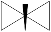
Fine control of small flows, often on instrument lines.
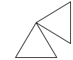
Inlet and outlet at 90 degrees, so the valve also turns the pipe.
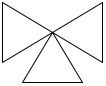
Three ports: splits one flow into two, or picks between two.
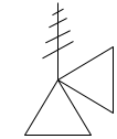
Opens on its own when pressure gets too high. The zigzag is the spring that holds it shut.
The symbol on top of a valve says what moves it.
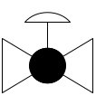
The dome is a diaphragm driven by air pressure. The controller moves the valve to any position, not just open or shut.
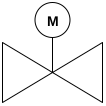
Opened and closed by an electric motor (M).
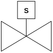
Snapped open or shut by an electric coil (S). Fast, on/off only.
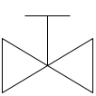
The T is a handwheel or lever: someone turns it by hand.

The most common pump: a spinning impeller in a round casing. Liquid leaves through the outlet at the top.

Two meshing gears push a fixed amount per turn. Good for oil and other thick liquids.

A rotating screw moves the liquid. Gentle on viscous or solid-laden fluids.

Rollers squeeze a hose; used to dose chemicals accurately.

Raises the pressure of a gas. The narrowing lines show the gas being squeezed.

Moves air or gas at low pressure.
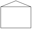
A tank at atmospheric pressure, flat bottom and cone roof.
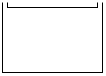
The roof floats on the liquid, which cuts vapour losses. Used for crude oil and fuels.
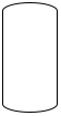
A closed vessel with rounded (dished) ends that can hold pressure.

The same lying down; often a separator, an accumulator or a fuel tank.
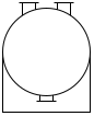
Holds liquefied gas such as LPG under pressure.
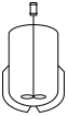
A vessel with an agitator inside and a heating or cooling jacket around it.
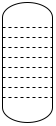
A tall vessel with trays or packing inside, used to separate mixtures, for example by distillation.
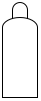
A portable bottle of compressed gas: nitrogen, CO2, oxygen.

Moves heat from one fluid to another without mixing them. The zigzag is the tube bundle.

Thin plates stacked together; compact and efficient, common in food and HVAC.

Boils liquid from the bottom of a column and sends the vapour back up.

Cools a process fluid with air blown over finned tubes.

Cools water by evaporating part of it into the air.
Instruments are drawn as bubbles with a tag inside, such as PT-101. The line through the bubble says where the instrument is; the shape says what kind it is.

A plain circle: mounted in the plant, on or near the pipe. A local gauge or a transmitter.

A line through the middle: in the main control room, where the operator can see it.

A double line: on a panel out in the plant, such as a compressor control panel.

A dashed line: in the control room but out of the operator's sight, for example inside a cabinet.

A circle in a square: a function of the distributed control system, shown on the operator's screen.

A hexagon: a calculation done in a computer, such as a flow total or an optimizer.

A diamond in a square: logic in a programmable logic controller, such as an interlock or trip.
The line style says what travels along it.

A heavy solid line is a pipe carrying the process fluid. An arrow shows the flow direction.

A dashed line: a wired signal, such as 4-20 mA from a transmitter to the control system.

A line with double slashes: an instrument air signal, often 3-15 psi to a valve.

A line with L marks: a signal carried by hydraulic oil.

A line with crosses: a sealed capillary, as on a filled temperature or pressure gauge.

A line with small circles: data between systems, such as a fieldbus or a link inside the control system.

Joins a larger pipe to a smaller one.

Catches dirt before it reaches a pump or valve. The leg holds the screen.

A plate between two flanges. Turned one way it blocks the pipe completely; turned the other it lets flow through.

A flexible section, for example at a loading point or to take up vibration.

Absorbs movement as the pipe heats up and grows.

A float in a tapered glass tube shows the flow rate.

Measures flow from the pressure drop in a narrowed section of pipe.
The letters inside a bubble say what the instrument measures and what it does. The first letter is the measured value; the next letters are its functions. The number is the loop, so FT-101 and FIC-101 belong together.
| Letter | First letter (measures) | Next letters (does) |
|---|---|---|
| A | Analysis (pH, O2, gas) | Alarm |
| C | Control | |
| E | Voltage | Sensor (element) |
| F | Flow | |
| I | Current | Indicate |
| L | Level | Low (in alarms: LAL) |
| H | Hand (manual) | High (in alarms: LAH) |
| P | Pressure | |
| S | Speed | Switch |
| T | Temperature | Transmit |
| V | Vibration | Valve |
| Z | Position |
PT-101: pressure transmitter. TI-205: temperature indicator (a local gauge). FIC-110: flow indicating controller, usually in the DCS. LAH-300: level alarm, high. PSV-12: pressure safety valve.
Take a photo of a sketch or a red-lined print. Sketch2scheme turns it into an editable draw.io diagram you can clean up and share.
A process flow diagram (PFD) shows the main equipment and flows, often with temperatures and pressures. A P&ID adds every pipe, valve and instrument and how they are controlled. Plants are built and run from P&IDs.
Where the instrument is. No line: in the field. One solid line: in the main control room. Two lines: on a local panel. A dashed line: behind a panel, out of the operator's view.
ISA-5.1 for instruments, tags and signal lines. Equipment and valve shapes follow ISO 10628 or company standards, which is why each P&ID set comes with its own legend sheet.
Yes. Download the draw.io library, open it in draw.io (free, in the browser or on desktop) and drag the symbols onto your drawing.
Symbols are drawn with draw.io (diagrams.net), which is open source. Use them freely in your own drawings, documents and lessons.