

Wire
Also: conductor
A line is a wire. Its length and bends on the drawing mean nothing; only what it connects matters.
Circuit diagrams and wiring diagrams use the same small set of symbols. Learn about 60 of them and you can read almost any schematic, from a car stereo to a solar setup.
Two standards are in use. The US uses ANSI/IEEE symbols (a zigzag resistor), while Europe, the UK, Australia and most of Asia use IEC 60617 (a box resistor). Where they differ, both are shown.
Free. In draw.io, open the library with File › Open Library from › Device. Each symbol below also downloads as SVG, or copies straight into draw.io.
A line is a wire. Its length and bends on the drawing mean nothing; only what it connects matters.

A dot where lines meet means the wires are connected.

Lines that cross without a dot are not connected.

An older way to show wires that cross without connecting. You still see it in car and appliance manuals.

An open circle marks a point where an outside wire connects, or a point to measure.

A connection to the earth: a ground rod, or the earth pin of a mains socket. Fault current flows here.

The 0 V reference of a circuit. Every ground symbol on a schematic is connected to every other one.

A connection to the metal frame or case. In cars the body is the negative return, so most loads are wired to it.

A row of screw terminals where wires are joined. Each box is one terminal.
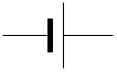
One battery cell. The long line is positive (+), the short line negative (−).
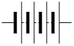
Several cells in series. Drawings rarely show the real count: a 12 V battery is often drawn with two or three cells.

A source of constant voltage, such as a bench power supply. The + marks the positive terminal.

Alternating voltage, such as mains power or a signal generator. The wave inside means AC.

Pushes a fixed current, whatever is connected, in the direction of the arrow. Mostly seen in textbooks and analog design. Some European drawings use two overlapping circles instead.
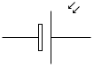
Turns light into DC power. The arrows show light coming in. A whole solar panel is drawn the same way.
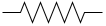
Limits current. The value is written next to it in ohms: 220R, 4k7 (4.7 kΩ), 1M.
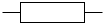
The same part, drawn as a box in Europe and most of the world.
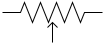
A resistor with a sliding contact (the arrow), like a volume knob. It has three terminals.
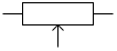
The same part in IEC style.
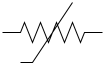
Its resistance changes with temperature; the bent line marks that. Used as a temperature sensor. Often labelled t°.
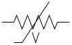
Conducts hard above a set voltage. Placed across a mains input, it absorbs spikes.
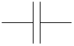
Two plates that store charge. It blocks DC and passes AC. Values are in farads: 100 nF, 10 µF.
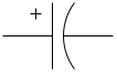
Must go in the right way round: + to the higher voltage. The curved plate is negative. Fitted backwards, it can burst.
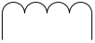
A coil of wire that resists changes in current. Values are in henries: 10 µH, 1 mH.

Two coils that pass AC from one circuit to another, stepping the voltage up or down. The lines between them mean an iron core.

The short IEC form: two overlapping circles, one per winding. Common on power and single-line diagrams.
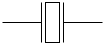
Sets an exact frequency, the clock for a microcontroller or a watch.
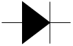
Current flows one way only, in the direction of the arrow. The bar is the cathode, the stripe on the real part.
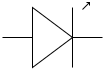
A diode that lights up. The arrows point out. It needs a resistor in series to limit the current.
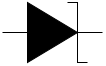
Used the "wrong" way round to hold a fixed voltage, such as 5.1 V. The bent ends of the bar mark it.
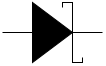
A fast diode that loses less voltage (about 0.3 V). Common in power supplies and solar chargers. The S-shaped bar marks it.
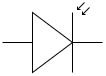
A diode that conducts when light falls on it. The arrows point in. Used as a light sensor.
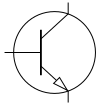
A small current into the base switches a larger current from collector to emitter. The emitter arrow points out.
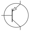
The same with the polarity reversed. The emitter arrow points in. It turns on when the base is pulled low.
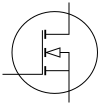
Voltage on the gate switches current from drain to source. The usual choice for switching a load to ground.
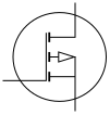
Turns on when the gate is pulled below the source. Often used to switch the positive side of a load.
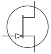
A transistor that is on until the gate voltage pinches it off. Found in low-noise audio and sensor amplifiers.
Switches and contacts are drawn in their rest position: as they are when nothing is pressed and no power is applied.

A simple on/off switch, drawn off. Current cannot flow until it is closed.

The same switch, drawn on.

Connects only while pressed, like a doorbell.

Connects the common terminal to one of two outputs, for example to pick between two batteries.

Connects the common terminal to one of several positions.

Cuts a whole circuit off so it is safe to work on. Not designed to switch under load.

A switch worked by a coil. A small current through the coil (the box) closes the contact; the dashed line links them.

The coil on its own. Its contacts are drawn elsewhere and carry the same name, such as K1.

Open at rest. Closes when the relay is energized or the button is pressed.

Closed at rest. Opens when the relay is energized.
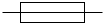
A thin wire that melts when the current is too high, so the wire it protects does not overheat. Rated in amps.
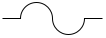
The same part in the US style.

Trips on too much current, like a fuse, but can be reset.

The IEC form: a switch with a cross on its contact.

Any light: a cabin light, a headlight, a warning lamp. The circle with a cross is the most common form.

An older US symbol for an incandescent bulb: the loop is the filament.

A circle with M. A fan, a pump, a wiper or a winch motor.

A circle with G. On a car or boat diagram, this is the alternator.

Turns an electrical signal into sound.
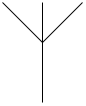
Sends or receives radio signals.

Measures current. Wired in series with the load, so the current flows through it.

Measures voltage. Wired across the part, in parallel.
Logic gates work with two levels: 1 (on, high) and 0 (off, low). A small circle on an output means the result is inverted.
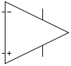
Amplifies the difference between its + and − inputs. Power pins are often left off the drawing.

Turns a higher, changing voltage into a steady one, for example 12 V in, 5 V out (7805, LM317).
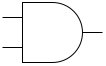
Output is 1 only when all inputs are 1.
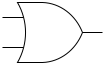
Output is 1 when at least one input is 1.
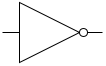
Output is the opposite of the input.
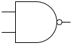
AND with an inverted output: 0 only when all inputs are 1.
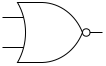
OR with an inverted output: 1 only when all inputs are 0.
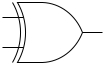
Output is 1 when the two inputs differ.
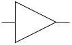
Output equals input. Used to give a weak signal more drive.
Start at the power source and follow the wires to each part and back to ground or the negative terminal. Current only flows around a closed loop.
Parts are named with a letter and a number. The value is written next to them. The letters are standard, so a quick look tells you what is on the board:
| Letter | Part | Example |
|---|---|---|
| R | Resistor | R1 = 10k |
| C | Capacitor | C3 = 100 nF |
| L | Inductor | L1 = 22 µH |
| D | Diode (LED often LED1) | D2 = 1N4007 |
| Q | Transistor or MOSFET | Q1 = 2N2222 |
| U or IC | Chip | U1 = NE555 |
| K | Relay | K1 |
| F | Fuse | F1 = 5 A |
| S or SW | Switch | SW1 |
| J or X | Connector | J2 |
A schematic (circuit diagram) shows how parts are connected electrically, laid out to be easy to follow. It says nothing about where the parts sit.
A wiring diagram shows real wires between real parts: which terminal, which wire colour, often the wire size. Car, boat and house wiring is usually drawn this way. Both use the symbols above.
Take a photo of the sketch. Sketch2scheme redraws it with these symbols as a clean, editable diagram you can download for draw.io, as PNG or as SVG.
They are the same part. The zigzag is the US (ANSI/IEEE) symbol; the box is the IEC symbol used in Europe and most other countries. Both mean resistor.
Only if there is a dot where they meet. Lines that cross without a dot are separate wires. Older drawings show a small hop where one wire jumps over the other.
Earth ground connects to the earth itself and carries fault current. Chassis ground connects to the metal frame or case. Signal ground is the 0 V reference of a circuit. In many small circuits they are all the same point, but on mains equipment and in vehicles they are kept apart on purpose.
Yes. Download the SVG of any symbol, or the whole set as a draw.io library, and use them in documents, homework or product manuals. The shapes come from draw.io, which is open source.
Symbols are drawn with draw.io (diagrams.net), which is open source. Use them freely in your own drawings, documents and lessons.